
- HOME > Technical Data
Magnetic Circuit Design Data
Calculation of Magnetic Field on Central Axis of Single Magnet
The intensity of the magnetic field on the central axis of single magnets such as ferrite and rare-earth magnets whose demagnetization curve be approximated by a straight line is found as follows.
1. Cylindrical magnet (Fig. 4-1)
The magnetic field intensity on the central axis at point B at any distance from the end face of a cylindrical magnet whose diameter is D and length (in the direction of magnetization) L is indicated by the symbol H(p).

2. Bar magnet (Fig. 4-2)
The magnetic field intensity on the axis of a bar magnet whose cross section is A×B and length (in the direction of magnetization) L is to be indicated by the symbol H(p).

By assuming P = -2/L, the Hd of the single magnet is found in each above. In this way the permeance coefficient is determined.3. Hollow cylindrical magnet (Fig. 4-3)
The magnetic field intensity on the central axis of a hollow cylindrical magnet whose outside diameter is Do, inside diameter Di and length (in the direction of magnetization) L is indicated by the symbol H(p).

- The magnetic field intensity is found by assuming P = -L/2
When two magnets of identical shape are placed opposite each other at a distance of 2P, the void central magnetic field intensity (Bg) is twice the value of H(p) in each of the above cases.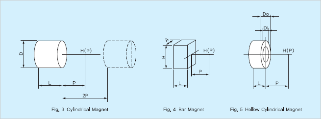
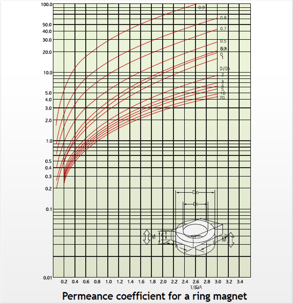
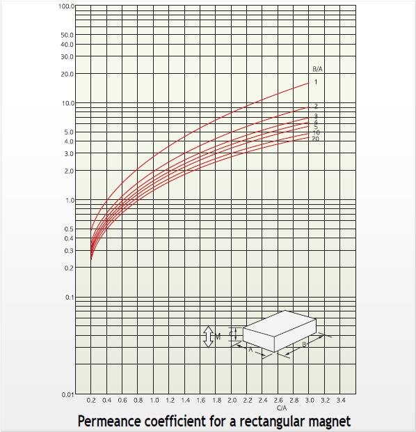
- Also, the permeance of a single magnet is expressed in the following graphs :
Measuring Methods
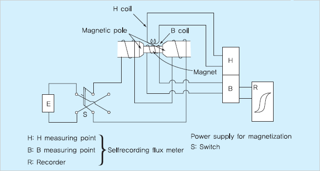
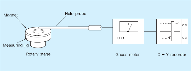
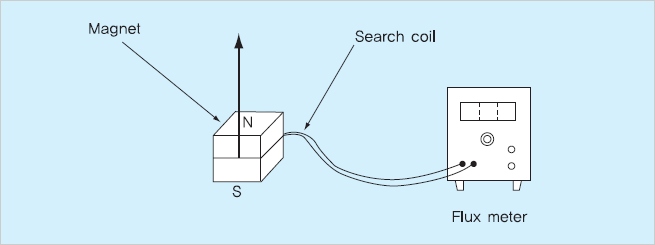
Measuring methods for the magnetic characteristics of magnets are illustrated below.1. Demagnetization curve (B-H curve)
2. Surface magnetic flux density
3. Magnetic flux volume
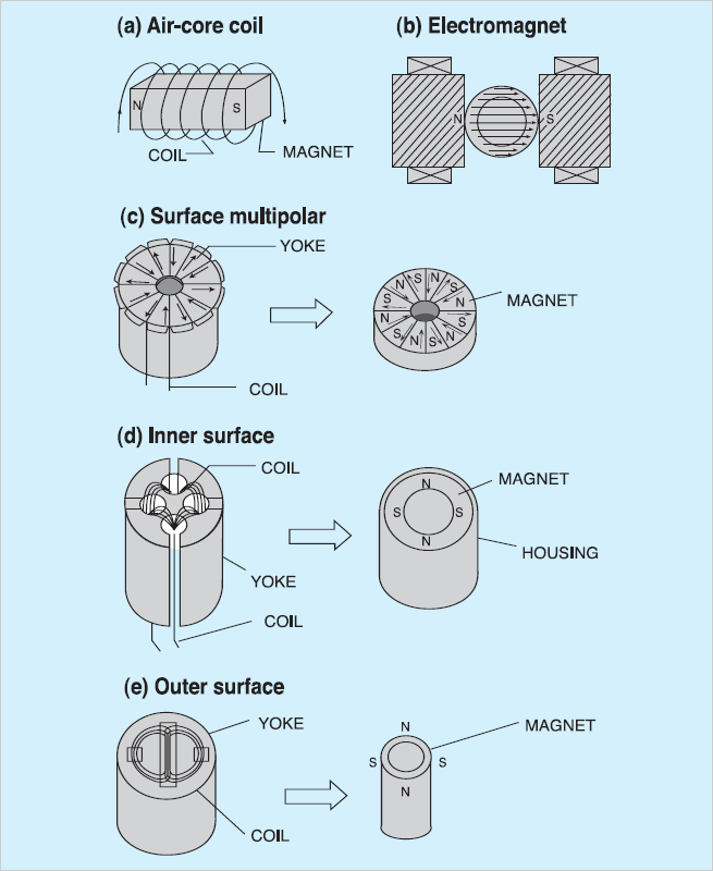
Examples of Magnetization
Various magnetization processes are available to meet application requirements.
Inquiries about special processes are most welcome.
For simple N and S magnetization hollow coils and electromagnets are useful.
For multiple magnetization or magnetization patterns of typical magnetization yokes are shown below
